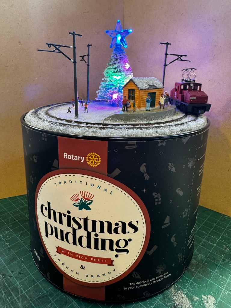
This Christmas micro layout was designed to fit neatly on top of a rotary Christmas pudding tin. Built in N gauge, the layout features an extremely tight track radius of approximately 60 mm.
To achieve the required curvature, standard flex track was modified by removing the sleepers. The rails were then carefully rolled to the correct diameter, after which PCB sleepers were installed to accurately hold the gauge. Once the geometry was locked in, the original flex-track sleepers were refitted in the gaps to restore a more conventional appearance.
The platform was 3D printed, then sanded and painted before installation. The station building is a Modelscene N Lineside Huts kit, part number 5185. After assembly and painting, aluminium foil was added to the interior to prevent light bleed, and a flickering LED was installed to provide a warm internal glow.
The traction poles are from the Greenmax 2183 Single Track Catenary Poles set and were painted to suit the scene. Overhead wiring has been intentionally omitted. At this radius it would be extremely difficult to install reliably, and it would likely be vulnerable to damage during handling.
Figures on the layout come from Noch sets 36821 Children in the Snow and 36926 Christmas Market, which suited the festive theme perfectly. The Christmas tree, while slightly overscale, was sourced from a local discount store. It had to be trimmed to roughly half its original height to fit within the confines of the tin.
Power is provided by two AA batteries, supplying both the track and lighting. The locomotive is a Kato Pocket Line engine, which runs reliably despite the tight curvature and low voltage power setup.
The baseboard construction involved laser cutting the baseboard from acrylic and plywood in layers that were then glued together. This should be strong enough to prevent warping and it sits nicely within the recess of the tins lid.
For the snow I used the Deluxe Materials BD29 Scenic Snow Kit, pretty much following the instructions, it’s applied like any other scatter material.
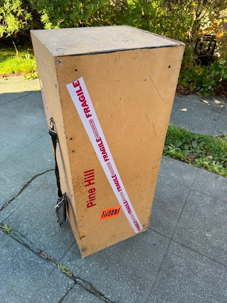
Layout packed away inside the tin.
Overall, this was a fun and rewarding project that explored the limits of micro layout design while creating a festive, self-contained railway scene inside a Christmas pudding tin.
Reflecting on the passage of time, my original micro layout, crafted in 2003, now stands at the ripe age of 20. I exhibited the layout at model shows in Wellington and Christchurch from 2003 to 2006. Recently, it resurfaced in conversation, prompting me to dust it off from storage and breathe new life into it. After some tender care, the locomotives are chugging along once more, though one required a new cab. Presently, my focus is on modernising the wiring and electrics to ensure the layout remains relevant and operational.
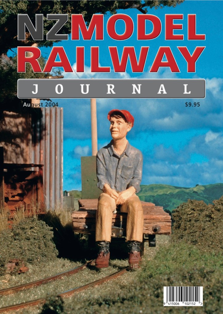
Pine Hill Estate layout in its transportation box as pulled from storage .Looking like a Halloween layout with spider webs.Cleaned up view from the campsite end of the layout.Gnat cleaned up and serviced. The driver needed some surgery to repair his hat.New cab being built. This engine had lost its entire can over the last 20 years.Gn15 on the front cover of the Model Railway Journal back in 2004.
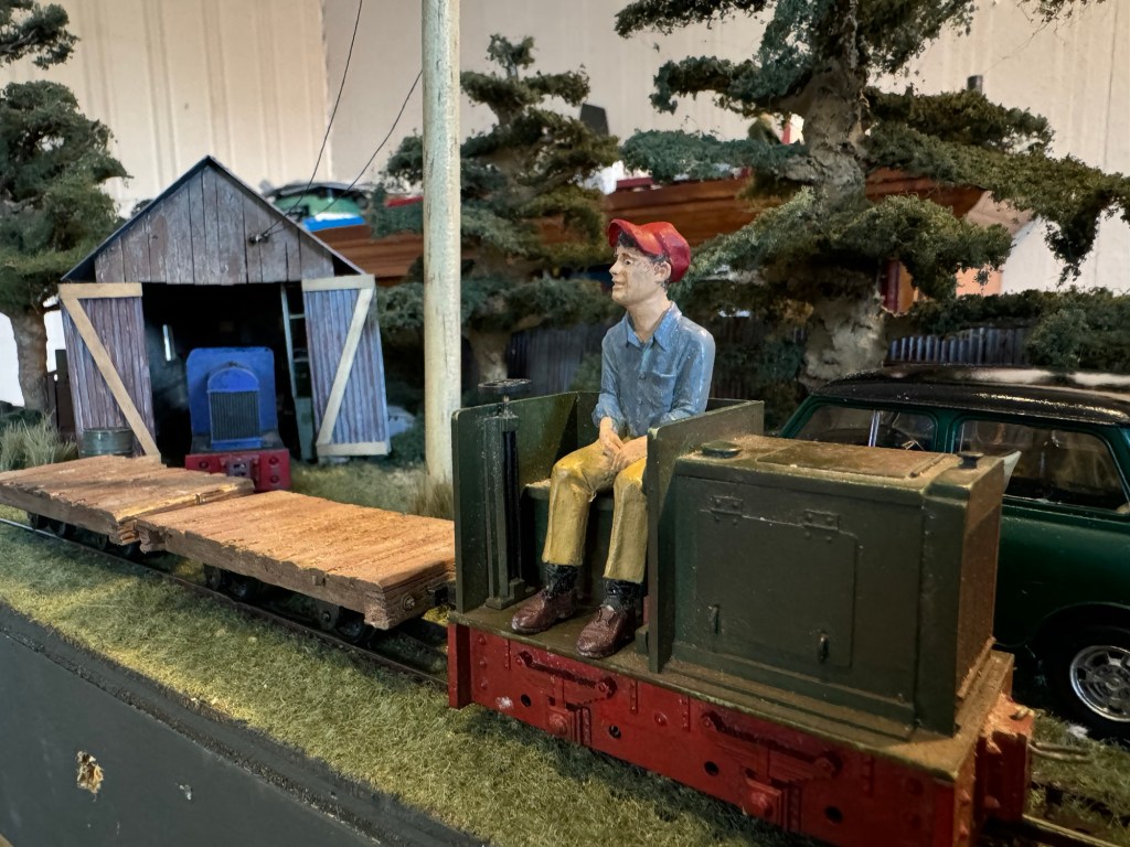
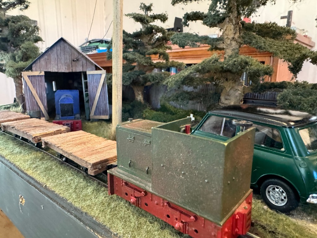
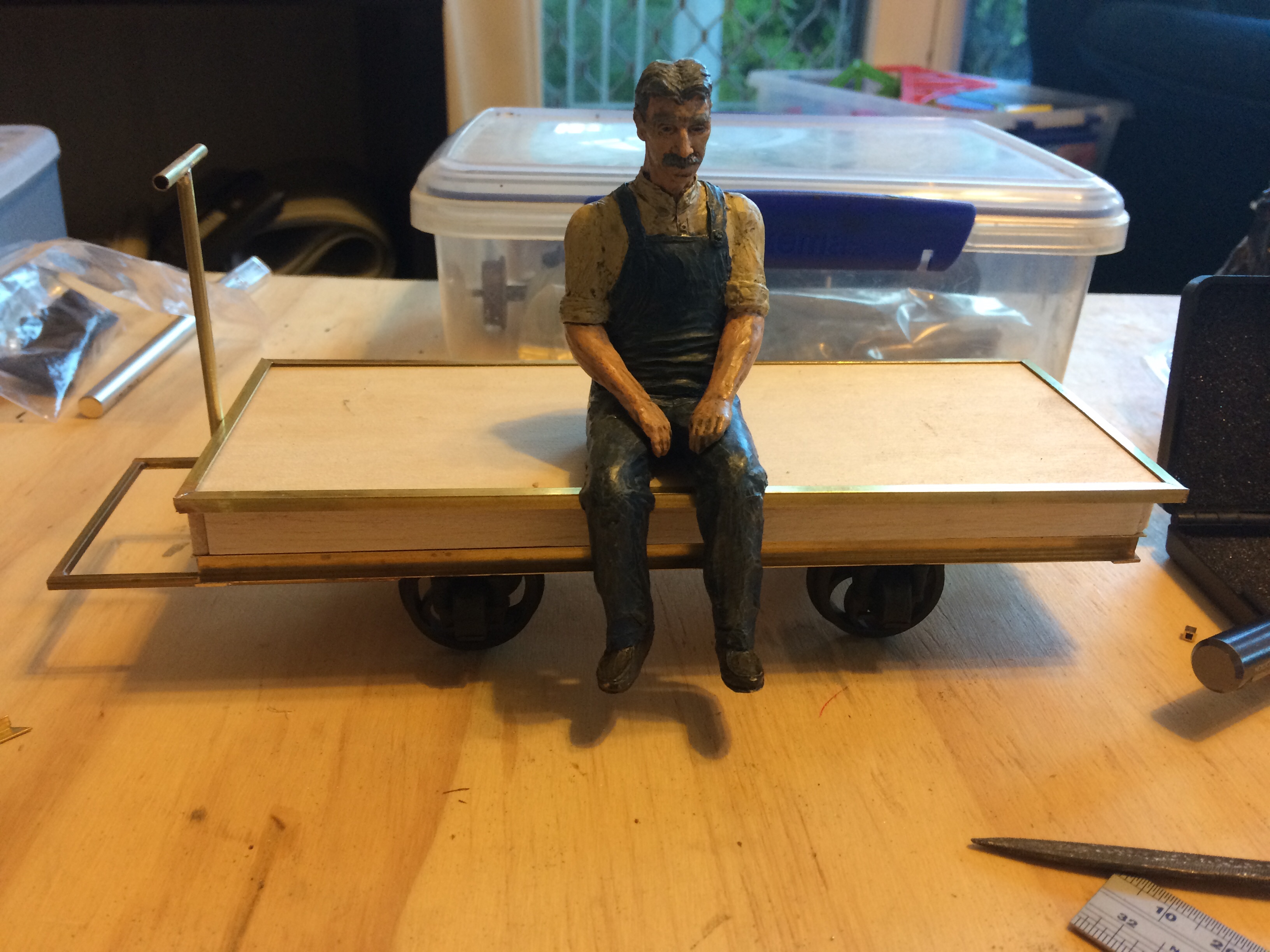
The Mk.1 motor trolley with the Tamiya motor and gearbox. The figure is a 7/8th scale resin casting.
The model has been designed in 1:12 scale to represent a NZR motor trolley. The model is intended to capture the essence of a motor trolley and isn’t a rivet counter accurate model of a specific motor trolley.
A motor trolley is a small railcar formerly used by track inspectors and maintenance staff to move quickly to and from work sites. Motor Trolleys were replaced by road vehicles with additional flanged wheels that can be lowered for travelling on rails, these vehicles are called hi-rails.
This project has been a test of Computer Aided Modelling with most of the components being laser cut or 3d printed. The machines I used to manufacture the motor trolley are:
The Atomstack X7 Pro laser cutter
The Voxelab Aquila 3D printer
I started designing this around a universal motor gearbox from Jaycar Electronics with version 1 of the motor trolley using this; however while it travels at a reasonable scale speed it takes a long time to travel around the track. To improve this a new drive train was designed using a RF-300CA motor that is designed for CD/DVD players. This motor has increased the top speed however it doesn’t have the torque of the Jaycar gearbox.
Supplies
Acrylic laser cut parts
3PDT center off toggle
3mm red LED
10mm warm white LED
2 x 150 Ohm Resistor
2xAAA battery holder
RF-300CA motor
SP08-2M sprocket
SP18-3M sprocket
90mm of chain
4x 3D printed wheels
2x axles 3mm x 102mm
4x bearings 683zz
2x 8BA x 20mm
4x 8BA x 6mm
2x M1.7 x 6mm
2mm brass rod x 110mm
Chain and sprockets were purchased from MOTIONCO https://www.motionco.co.uk/. All other materials were purchased from AliExpress or any of the model engineering suppliers. CAD file for the laser cutting and STL files for the wheels are available on Thingiverse .
Assembly
You will need to tidy up the laser cut parts to remove burrs with a file or some sandpaper. The holes in the body sides and battery shelf will need to be tapped to 8BA. The brim used by the 3d printer to ensure bed adhesion for the wheels will also need to be removed.
The axles being used to hold the side frames in alignment while they’re glued. The front of the chassis is at the top of the photo.
The frame is assembled by first pushing the bearings into the side frames and then, using the axles to ensure alignment, gluing them to the chassis. It’s important to make sure that the shorter end of the side frames faces the front so that the headboard can be installed.
Install the motor mount and support, ensure that these are straight. Once the glue is dry you can install the motor with the two M1.7mm screws. The holes are slotted and it’s best to install in the rearmost position to assist with installing the chain.
The assembled motor mount
Install the smaller sprocket on the motor shaft and align the sprocket on the axle. Install the chain by running around the sprockets and joining it on the large sprocket.
The body work is relatively easy to assemble. I used the headboard to hold it square while the glue dry’s. Leave the headboard to last as the top seat and headlight set’s the position for it. Make sure that the battery shelf is facing the correct way with the two holes towards the front of the motor trolley.
The headboard is glued to the body however make sure that you don’t glue the top seat down. The top seat is held in position with two screws that allows you to remove this to change the batteries.
The seat with the headlight holder. The bottom of the back handrail should sit on the battery tray when the seat is installed.
The seat top has the headlight and back handrail glued to it. The handrail at the back of the motor trolley is bent up out of 2mm brass wire. The handrail should be about 20mm above the seat. The two lifting rails can now be installed on the sides of the body with the 8BA screws.
This is a good point to paint the bodywork. I find that using an etch primer on the acrylic works well. Remove the motor, axles and bearings before painting. NZR motor trollies were traditionally painted in red with a white stripe on the front to improve visibility.
The motor trolley is ready to paint. I suggest removing the lifting rails and seat for painting.
With the bodywork painted it’s time to move onto preparing the electronics. The headlight is a 10mm LED however we don’t want the dome of the LED so this needs to be cut or filed down. You need to be careful trimming the LED as if the internal metal components are exposed the LED may not work.
The cut down LED being tested. When cutting the led down be careful that you don’t expose the internal metal connections. I trimmed mine to have just over 3mm above the lip.The cut down LED next to an unmodified LED.The basic circuit diagram showing the use of the 3PDT center off switch. The 3rd leg of the switch is used to turn on the head and tail lights.
Glue the battery holder onto the battery shelf with the wires facing forward. The motors I purchased came with a plug on the wire tails, I removed this to solder the wires directly onto the switch. You will need to leave enough slack on the wire connections to allow for the seat to be removed when replacing the batteries.
Wire up as per the above diagram, ensure that you orientate the switch so that pushing it forward makes the motor trolley go forward.
The motor trolley has proven to be fun to run between trains at the track and there are a number of alterations that could be done to this to improve the appearance, and operation.
I’ve kept the controls simple however it requires you to catch the motor trolley as it comes past, to remove this issue radio control could be fitted.
The headboard could be replaced with a handrail making it more like a M9 Fairmont speeder from the USA.
Mudguards could be designed and fitted over the wheels. I’ve left two mounting holes on each side for these if someone want’s to design them.
While this was designed for laser cutting I’ve added an STL for 3d printing the main components to the Thingiverse and Printables page. This is untested at the moment.
So I’ve invested in a 3D printer and have started printing some 3.5″ gauge rollingstock. There are some sources for some ready to print rollingstock that I’ve found on the internet. While 3D printed rollingstock isn’t suitable for passenger hauling it does look good running at the back of a train.
Wheels
Looking at options for wheels in 3.5″ gauge and there is little available commercially. The International Brotherhood of Live Steamers has the cad files with wheel profiles on their website. I’ve used this to create some basic wheels for 3.5″ gauge. Time will tell how these last running on the raised track at the club.
Most of the models require some additional materials to complete and you will need a supply of brass, bright mild steel rod for axles, bearings, BA bolts etc.
Ready to go Wagons to print
I’ve added some links to some ready to go files you can print for 3.5” gauge. Let me know if you come across any others.
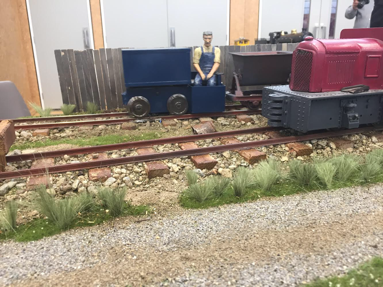
Pine Valley Siding is a new diorama/layout built to display my 7/8th scale trains. The layout features hand spiked track a stub turnout and enough room to run a small locomotive and two tippers back and forth.
The layout came together in the week before RailEx with the track and turnout being hand built during this time. The street lamp is scratch built with the lampshade being cut from brass sheet and the insulators being made up with beads from the craft store.
The night before the show I knocked up a shuttle circuit to get the train running back and forwards. This circuit worked well for the day however I’ll have a go at refining it to simplify the operation.
Pine Valley Siding on display at Railex November 2019
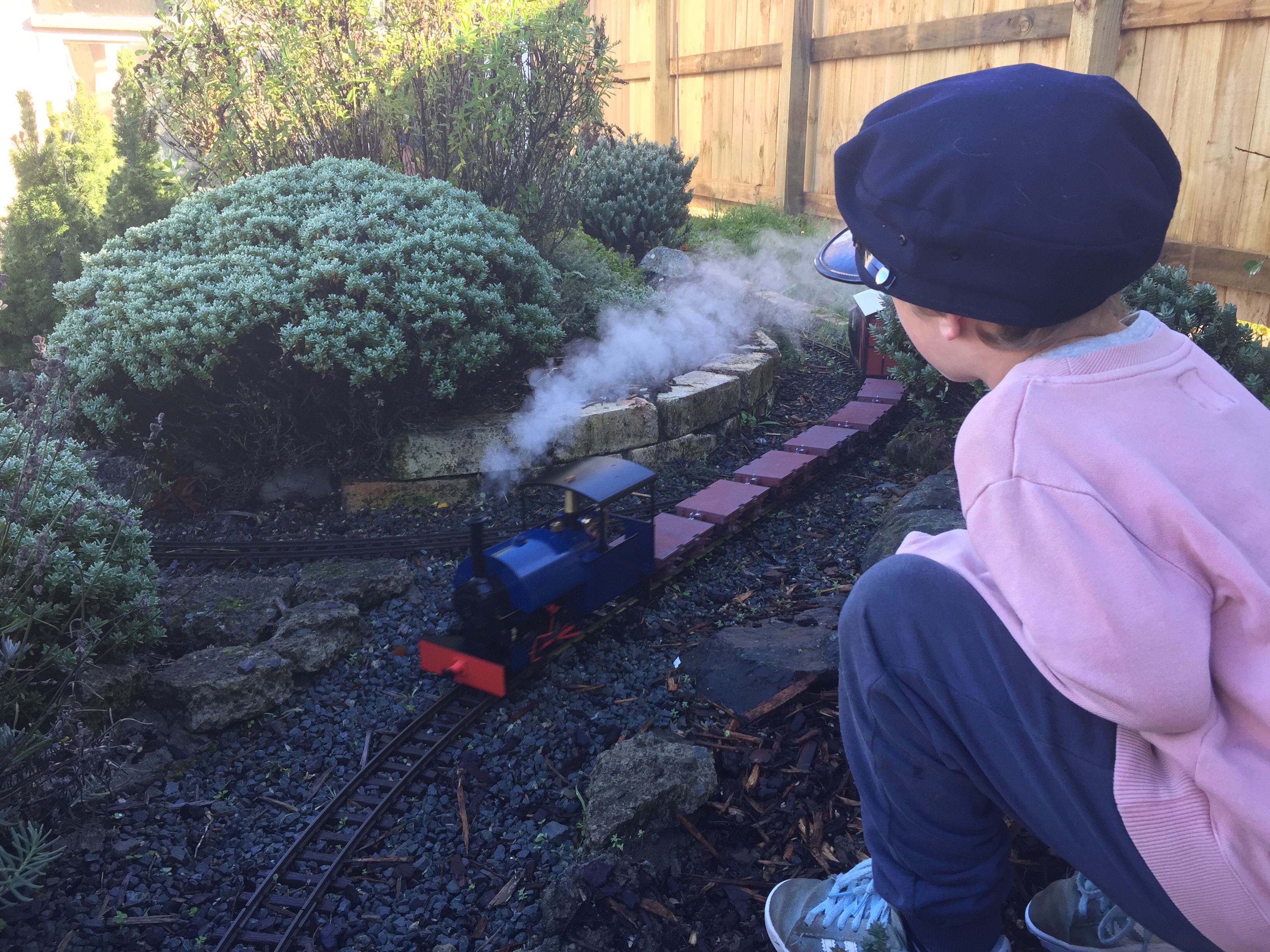
With the weather being now so great over the last few days we took the opportunity to steam up the Bagnall for a run.
Also did some maintenance on the line by installing a number of Split Jaw rail clamps around the top curve, spent some time easing the grade on the back straight and adjusted the tracks top and line in a number of places.
Maisie is a 4-4-2 GNR Atlantic Tender Locomotive in 3.5″ gauge. The model was designed by LBSC as a miniature replica of the Great Northern Railway’s “Large Atlantic” class.
The prototype C1 Class was designed by Henry A. Ivatt as an enlarged version of what became the LNER C2 Class. The principle of the design was to produce a powerful, free-steaming engine to haul the fastest and heaviest express trains on the Great Northern Railway.
Construction of the model was described in Model Engineer Vol. 72-76 and the book Maisie Words and Music.
Over the next few months I’ll be working on getting this locomotive back into steam.
References and Links
LBSC. (1952). Maisie words and music. London: Percival Marshall and Co. Ltd.
So I’ve brought my first garden scale live steam locomotive and what I didn’t find while researching what to buy was a list of what equipment was needed to operate the engine.
I’ve had some Mamod traction engines for a while and we have been running these as per the instructions that came with them. In retrospect some of the tools and equipment that we got for the locomotive would have simplified operating the traction engines.
So here is my rough guide of equipment that I brought and what I’ve found useful so far.
Water Syringe – The easiest way to water a cold locomotive or traction engine is with a syringe. One came with my locomotive however I purchased a spare from Aliexpress with a length of flexible hose. The hose allows me to empty the boiler of water after a running session.
Butane Canister Adaptor and Roundhouse gas filling adaptor – These need to be purchased to fill the butane tank on the locomotive. I’ve noticed that the butane gas canister adaptor can be purchased from Aliexpress just search for –
Steam oil & Metal – steam oil is essential to the long term life of the locomotive. I got a bottle of steam oil and the Accucraft AP29-201 metal syringe from Argyle locomotive works. The metal syringe makes it really easy to get the right amount of steam oil into the lubricator and if you over fill the lubricator you can remove a small amount.
Oil can – For lubricating the motion I’m using the Reilang Pocket Oiler. This provides a bit more control than just the bottle of 3 in 1. I did try another pocket oiler however it proved useless compared to the Reilang product.
Rolling Road – I got the Accucraft Rolling Road for testing the engine this has proved useful for learning to run the engine as you can steam it in one spot. It’s also proved useful when building non-live steam models as you can test run the mechanism while ironing out any issues.
Goodall Valve & Water Top Up Bottle – a Goodall valve is basically a simple clack or one way valve that allows you to pump water into the boiler while it is still under pressure. This allows you to refill the boiler and extend your running time. On my Accucraft locomotive the fuel tank is sized to suit the boiler size so you run out of gas before you run out of water. However being able to maintain steam pressure saves time as its just a mater of topping up the gas and steam oil to keep running.
Hand tools –
Rags – Without a chuffer when the locomotive starts moving you get oil and water coming out the stack. The easiest way to prevent this is to hold a rag over the stack when you clear the condensation from the cylinders. There’s quite a bit of heat coming from the stack so make sure the rags are flame retardant/heat resistant. These are also good for wiping down your locomotive after an operating session.
Field box/flight box – I’ve been looking for a suitable toolbox to store all the above. In the end I found that in the remote control aeroplane world they have what is called a field or flight box. These field boxes are all set up for model aeroplane requirements, although I found you can purchase a field support box from Loco Boxes in the UK. Having a look around I decided that the best option will be to build my own field box suited to my live steam application once I work out exactly what I need.
When we were building the garden railway I was maintaining a thread over on G Scale Central. At some point I’ll look at transferring this over to this new site for the sake of completeness until then to see more on the early days of the Pine Valley Estate Railway visit the thread over at:
The only problem with 7/8th scale is the equipment is often too large to operate on friends G scale layouts. I had a look around for a small prototype that would fit within the the G scale loading gauge. I found a suitable prototype in the HAWE a small self propelled flat wagon used in the Netherlands. I found a Geocities page with heaps of photos of the prototype and some technical information. The key dimensions for building my interpretation of the HAWE are 3300mm long, 1000mm wide.
The model isn’t intended to be a exact scale model the goal was to capture the look and feel of the HAWE. I decided to build the model from brass sections which is a first for me however it gives the model some weight.
For the driverS step I got some neat 1:14 scale tread plate from Aussie RC. Aussie RC also had 3D printed oil drums that supplied a suitable load. Without the oil drums there is no real reference to scale and it may be mistaken for a G scale wagon when out visiting.
Mechanism
I purchased a N20 motor with metal gearbox from Aliexpress. The N20 motor I ended up using is 3v with a no load output speed of 200rpm. I’m really impressed with the quality of this cheap motor and will be using these in future projects.
The motor output is connected to the axles using sprockets and chain from MotionCo. Wheels, axles and axle boxes are from Binnie Engineering and apparently 30% glass fibre 70% nylon. They should last in this sort of low power application however time will tell.
My model HAWE true to prototype is battery powered and in the principle of KISS the control is a simple on/off switch.
This has been my first attempt at scratch building a mechanism. The 1000 rpm version of this motor doesn’t have enough torque so the model isn’t the fastest item in our fleet although it travels at a nice prototypical speed. Overall this mechanism seems to operate well and I’ll be using a similar set up on my next project.
Materials
In case anyone else wants to give building one of these a go here are the links to where I got my materials.